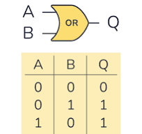
- When both inputs (A, B) are 0 (switches are open) output C is 0 (lamp is OFF)
- When A is in logic state 0 (switch A is OPEN) but B is in logic state 1 (switch B is CLOSED), the output C is in logic state 1(lamp is ON)
- Lamp would be also ON when A is CLOSED and B is OPEN.
- And again lamp would be ON when both switches are CLOSED.
- IT IS SO BECAUSE AN OR GATE IS EQUIVALENT TO A PARALLEL CIRCUIT IN ITS LOGIC FUNCTION.
- A + B = C , according to Boolean algebra, OR gate performs logical addition and its truth table can be written as
- Now it is important to understand that ‘+’ sign in Boolean algebra does not stand for the addition as in case of the ordinary or numerical algebra.
- So the ‘+’ sign indicates OR operation.
- Then in logic algebra, A+B=C means that if A is true OR B is true, then C will be true. IT DOES NOT MEAN HERE THAT SUM OF A AND B EQUALS C.
- The other equation could also be written as AUB= C or AVB= C
- The meaning of last three logic additions is that output is 1 when either input A or B or both are 1
- The first addition implies that output is 0 only when both inputs are 0.
YOU CAN BE RICH OR YOU CAN BE POOR
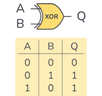
- In this gate, output is 1 if its either input but not both is 1.
- And output is 0 only when inputs are the same.
- This logic gate has output 0 when inputs are either all 0 or all 1.
- This gate works on the Boolean equation – A ⊕ B = C
- The previous switching circuit shows switch position A and B will individually light up the lamp but a combination of A and B is not possible.
EXCLUSIVE OR GATE


- YOU CAN BE RICH OR YOU CAN BE POOR – > Obviously you cann’t be both at the same time.
- This circuit is also called an inequality comparator or detector because it produces an output only when the two inputs are different.


